Page 1 of 1
Electrical Question
Posted: Wed May 22, 2019 12:50 pm
by Lee
Hi ... I am completely re-wiring our -170 and in back of the instrument panel, just above the overhead/instrument panel light switch and dimmer, I found what appears to be a tubular resistor (about two inches long) ... I find no mention of this in the -170 electrical guide that I could see. One wire was attached to it and that in itself was not attached to anything ... the wire was several inches long and had electrical tape wrapped around it. Any ideas as to what this is for? We have a 1954 B serial 26112. Thanks ... Regards/Lee
PS What led to this was some of the wires I saw initially showed indications of heat damage and I thought it prudent to replace the wiring ... plus I am adding newer avionics and went all electrical ... Garmin G5s, 430WAAS, Appareo Stratus, LED lighting, etc. I know ... not original but when I got the airplane, it had a number of STCs which I liked ... added more.
Re: Electrical Question
Posted: Wed May 22, 2019 1:19 pm
by Lee
Hi ... I think I just answered my own question. A further look at the schematic and I noted a 10 watt 60 ohm resistor ... makes sense. If anyone has other ideas, please advise!

(Also explains a missing wire off of the rheostat. I noticed the last time I flew the airplane at night that the compass light was inop figuring it was a burned out bulb. Thanks! Regards, Lee (N1967C)
Re: Electrical Question
Posted: Wed May 22, 2019 2:54 pm
by GAHorn
OK, well you figured out the compass light resistor, but the rheostat with a "missing wire"... I'm not clear about. Are you saying that one end of the wire-wound rheostat has an un-used terminal? Or, are you saying that no wire(s) are attached to it at all?
Rheostats are usually mfr'd to operate with clockwise or counterclockwise operation, and allow the installer to make that selection...based upon which END of the wire-wound element is chosen to attach to. The circuit runs from one of the wire-wound terminals, through the windings, then via a brush-block to the central terminal which is rotated by the knob. By rotating the knob, that central terminal/bush-block slides along the wire windings to increase/decrease current via the resistance wire in the windings.
Does that help?
Re: Electrical Question
Posted: Fri May 24, 2019 2:56 pm
by Lee
The rheostat had a wire attached to the left hand terminal (looking forward at the installed rheostat) no wire attached to the center terminal and no wire attached to the right hand terminal although, at one time there had been a wire attached to the right hand terminal based on the hole in the tab being soldered over ... makes no sense. I suspect that a wire had either been removed or broken away. I do not recall ever using the lights ... and to be honest, in removing the old wires, I may have tugged on one when I should not have and separated a wire from the rheostat although I tried to be careful in removing old wire. I did find several wires that had no end or beginning attachments ... they were either taped or had heat shrink tubing on the ends. I intend to use the rheostat only for the overhead instrument lights for nostalgia. (I'd like to replce the bulbs with LEDs but have not found any yet that are suitable unless I am missing something) The primary instruments (EI and Garmin) have their own internal lighting and are controlled by a separate EI controller. The Airpath compass is being replaced with either a vertical card or an SIRS Navigator. If the compass light resistor is not needed, it is coming out. I am amazed at the weight of the old wires I have removed. By the way, an article in The 170 News, Second Quarter 2010 by Richard Terrill is what led to my decision to re-wire the airplane and install bus bars (main and avionics) and push-pull CBs. The information from you all in the Forums and articles in The 170 News have been a lot of help. Comments welcome! Thanks ... R/Lee
Re: Electrical Question
Posted: Sat May 25, 2019 1:20 am
by n2582d
Lee,
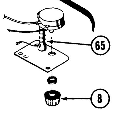
Is what you are looking at item 65 on fig. 42A of the IPC? It should be mounted on a plate just below the throttle. The illustration is a bit confusing in that item 8 is not just a knob. It is the rotary rheostat for the panel lights which has the knob included as part of the assembly. Item 65 is a fixed resistor for the compass light.

- Ohmite Resistor